
Click here for a larger "before" view of the front half.
A Basement Home Theater
As of this time (May 2013) the project has been ongoing on and off for seven and a half years.
Since so many others have published diaries of their remodeling projects, we did not want this web page to be "just another diary". So we have included some minutiae, describing some of the trials and tribulations, the revelations and the pitfalls, the good, bad, and ugly, and even some of the pet peeves.
Considerable effort has been made to keep the cost down. We are not installing much trim or things like wainscoting and crown moldings. We did not include every conceivable wire or cable that a future homeowner might possibly want.
Quick Clicks to Topics
Start at the Beginning
Picture Show (Photos by Flickr)Overview
Floor Plan
Walls
Framing
Drywall
Insulation
Soundproofing
Doors
Floor
Ceiling
Wiring
Power
Lighting
Audio
Video
Security
Ventilation
ScreenOur Living Room (not the puppet show)
Video Hints
Video Glossary
Unrelated Topics
Quick Overview, Before and After
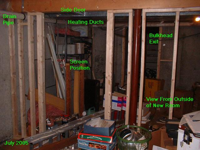
Some of the wall framing is underway in these pictures which were taken in July of 2005. We didn't have any pictures of the basement before any construction had begin.
Click here for a larger "before" view of the front half.

Click
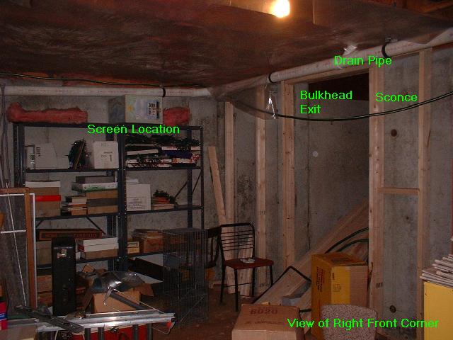
here for a larger "before" view of the front corner

Click
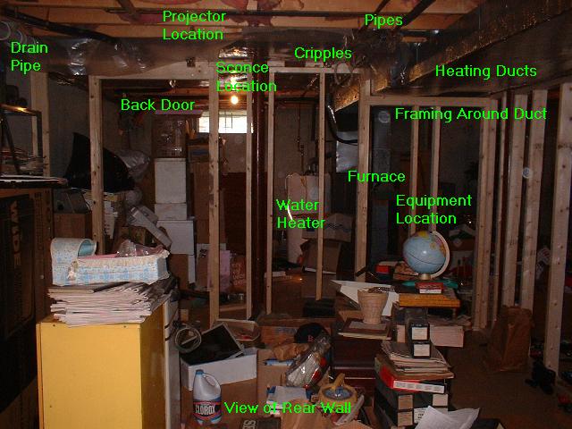
here for a larger "before" view of the back side
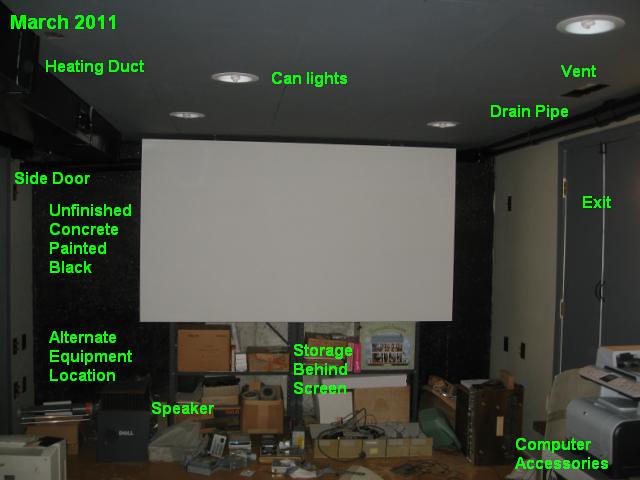
The next few pictures were taken in March of 2011

Click
here for a larger current view of the front side

Click
here for a larger current view of the back side.
In the late 20'th century, when movies on video tapes and video disks could be rented conveniently, people started to build elaborate sound systems if not entire theater rooms in their homes. Larger TV screens were becoming available at reasonable cost too, so folks could experience movies close to the way they were shown in commercial theaters. Home theaters never caught on before VCR's because very few movies were available on Super 8 films for rent. Setting up the projector and screen for "home movies" was more like a once in a year event rather than a weekly if not more frequent event.
Some folks still say that "a living room is not a theater and a theater is not a living room." We disagree. Especially for those with limited space, an excellent theater environment can be had in the living room if one so chooses.
How The Project Started
The project began in 2005 when we purchased a slide projector sized video projector "on impulse" At first we saw a Panasonic model AE300 LCD 1280x720 "720p" projector at an attractive price but we settled on the next generation model, a Sanyo PLV-Z3 (the Sanyo 'Z2 was equivalent to the Panasonic AE300).
Shortly after we got the projector, its sales price was reduced and not too long after that a yet newer generation model, the 'Z4, together with Panasonic's competing AE900 came out for approximately the price we paid. All of the models named were "720p" three panel LCD projectors.
The first viewing tests were done using the living room wall behind the sofa. The best location for a screen would be kitty-corner on the other side of the living room permitting viewing from both the sofa and through a hallway from another room. But a ceiling mount for the projector would interfere with a light fixture. Soon the idea of a separate theater room came to mind. It was probably just as well that we did not wait for the next generation projectors (Sanyo 'Z4 and Panasonic '700) as we would then not have gotten started on the theater room construction as quickly.
These projectors were also categorically called "front projectors" to distinguish them from (box like) rear projection TV sets. One requirement common to all front projectors is a darkened room, just as is needed for a Super 8 projector or a slide projector.
So some die hard home theater enthusiasts say that a home theater must have a front projector, a screen on the wall, and be "darkenable". Again we disagree. Movies can still be enjoyed under other conditions. The only standard for a home theater published so far (2009) was from back when almost all TV sets used cathode ray picture tubes and projection TV's were big bulky boxes. It called for a screen that showed the entire picture content of wide screen movies at least two feet diagonally, and with sound from left and right of the screen and from behind.
We will not argue with the idea that cropping the sides of a wide screen movie picture to better fill a not so wide screen violates the theater experience. This "pan and scan" cropping has also been done for 16mm and 8mm film versions of wide screen movies as produced for home showing.
Note: In 2013, flat panel direct view TV sets are quite common as the primary display device for a home theater. Fifty inches (diagonal) is quite common for a low cost theater, 60" for an intermediate installation and 80" sets are available for a deluxe installation. Full room darking is not needed with these although somewhat subdued room lighting is desirable.
Choosing the Location
A basement location was natural and ideal since there is no need for windows and daylight, while a windowed room would need opaque curtains. At the start of this project the basement was completely "unfinished"
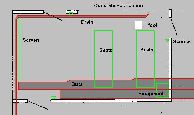
The basement is about 35 feet long by 25 feet wide on the inside. We allocated a space for the theater about 20 feet long by 12 feet wide, running lengthwise in the back half of the basement. The room's right wall corresponds to the house's rear foundation wall. The furnace is outside the theater room back wall and the laundry area is outside the theater left wall. There are two small typical eye-level basement windows on the house's right foundation wall not part of the theater room.

Click
here for a larger view of the original floor plan.
The city required permits for the whole project -- a general building permit, an electrical permit, and a mechanical permit for certain required ventilation equipment. The city also required a permit for building a storage shed in the back yard so we combined that with the theater project. One result was that building of the shed slowed down the building of the theater.
For this project, our first rule was that no pipes or other utilities would be relocated. Many other homeowners did relocate these items as part of basement remodeling projects. In our case, the main heating duct and accompanying return air duct ran lengthwise along the left side of our proposed room. This limited headroom to slightly over six feet. We felt that we could arrange at least eight seats with adequate aisle space and no obstruction of the view caused by the ducts. The main drain pipe ran along the ceiling lengthwise down the other side (right side) of the room and continuing down the front of the room. We left it exposed but the next owner of the house could enclose it in a "soffit". The screen hides most of the drain pipe continuing along the theater's front wall.
The nearest rest room is on the next floor up (first floor). We did not include a basement rest room as this would have greatly increased the project cost and also have required an additional permit, for plumbing.
Walls -- Defining the Theater Room
Three non-load bearing framed walls were built to form three of the room boundaries. The fourth room boundary (the room front wall) is the unfinished foundation which abutted the unexcavated ground under an enclosed breezeway and was therefore not a real exterior foundation wall. One framed wall, the right wall, with a doorway corresponding to the bulkhead and near the breezeway end, hides and insulates the rear foundation wall. The other long wall (left side) is directly under the center beam for the house and encloses the metal supporting columns. It has a doorway near the breezeway end of the house, or at the front left of the new room. The third, short, wall, which forms the back of the room also has a doorway.
The intent was to put shelving and then a curtain and then the screen at the (northwest) end of the room abutting the breezeway. Although there was space on either side of the screen for video equipment, neither side had extremely large amounts of space. Both a floor standing speaker system and the electronics would not fit together. The final design was intended to have most of the electronics at the inner rear corner.
The stud framing is fastened to the floor with construction adhesive. Masonry nails in the sole plates also help hold the framing in position although, without an explosive nailing gun we could only drive the nails into the concrete floor an eighth of an inch or so.
Unfortunately we were not very accurate in cutting the studs for the framing given that the basement floor was not level. There is a gap, as much as a quarter of an inch, in places between the top plate and the floor joists above. We are unsure of whether problems might arise if the floor adhesive failed, stud shrinkage occurred, and vertical play allowed the bottom edge of the wall framing to float free off of the floor. Some wood shims were glued in place here and there above the top plate.
The right wall (against the back foundation) was a typical wall running across the floor joists. We started by nailing a 2x4 to the joists. This would ultimately form part of a double top cap for that wall. At the floor we used a single pressure treated sole plate. At first only about ten feet of studded wall were planned, extending across the bulkhead exit where an exit door would be installed and leaving much of that foundation wall exposed. To provide added wall insulation required by code, the new construction was extended to cover the full 20 foot length of the foundation wall within the new room. The stud framing was built in sections no more than eight feet wide for ease of assembly and positioning, with studs at each end that became double studding where sections met.
The back and left side walls could be considered typical walls running parallel with and directly under the floor joists. These have single top caps. The left wall was positioned directly under the house center beam consisting of three side by side 2x12's. These walls' framing was also built in sections, this time necessitated by the columns that were to be enclosed within the walls. Sections end in single studs at the front concrete wall and at columns, with double studs (king and trimmer) at door openings. Framed corners have three studs although this is not exactly triple studding. At a corner, each wall section has one stud at the end, and one more stud is added as a nailer for drywall on the inside corner. It is not considered proper or customary but we had separate framing sections coming up to each side jamb of the interior doorways. The header for the rear door was a separate piece that fit up against the joists above with no cripples. There was insufficient headroom for any kind of header for the left side door and the door casing there fit right up against the existing house center beam. To allow pipes fastened to and running perpendicular to the joists to pass through, the rear wall framing was built shorter than the floor to joist height (by about 1-1/2 inches). Blocks cut from 2x4's are used as cripples and positioned horizontally to hold the cap to the joist above. Additional framing work including a section of lowered double cap was done to allow the ceiling mounted heating ducts to pass through the back wall. Just past the heating ducts in the inside corner, the rear wall is fastened only to the side wall which in turn is fastened to the house center beam. There is no clearance in that corner for the new framing to reach the joists above.
The columns and other obstructions made it impossible to maintain a simple 16 inch stud spacing although the left wall under the center beam comes close. We started to lay out a 16 inch spacing with additional studs added where needed but some miscalculations resulted in the 16 inch spacing "getting out of phase". For the (right side) wall fastened to perpendicular joists, the studs were offset from the joists by 1-1/2 inches so the caps could be nailed directly as opposed to toenailed to the joists.
Where pipes in the ceiling ran over to and up the exterior (northeast) wall we constructed framed access openings in the stud framing as wide as the stud bay consisting of interrupting the cap fastened to the joists and framing a separate double plate about nine inches lower. Enough space was provided so that if repairs were needed, a plumber could reach into the area in the vicinity of the house rim joist as if the basement had not been finished. Removable panels would be added later to cover these openings.
Installing Projector and Screen
Like many home theater builders, we hung the screen early in the project. Admittedly this slowed down the construction as, typically, time was spent watching movies rather than working on the room.
With today's emphasis on wide screen movie presentation, the typical roller shade screen used decades ago for slides and (Super 8) home movies is no longer considered large enough. Typical home movie screens from back then correspond to 40 to 50 inch TV sets of today. Our screen is a do-it-yourself item. We did not think of exact measurements but rather made the screen approximately 100 inches in diagonal measurement in an approximate 16 by 9 aspect ratio. We used 1x4 lumber for a frame and white "blackout cloth" for the screen itself. Many long discussions have taken place about whether the cloth surface should be painted, let alone painted silver or gray. We felt that the existing white surface was adequate. Blackout cloth is often used for movie screens because it is opaque, thus not "wasting" the projector's light output behind the screen.
We used 45 degree mitered corners for the screen frame. We cut the miters using an unusual angle so the frame, when laid flat on the floor during assembly, would have the perimeter tilted up slightly. This would prevent the cloth from touching other parts of the frame and having wrinkles show through. The screen frame parts were glued only. We felt that the polyurethane glue was sufficient except that two years later we found that one of the joints had failed although it was still held together by the stapled cloth.
The cloth was simply folded around to the back of the frame and stapled there.
There really is not much to say about rigid framed screens versus roll up screens versus screens painted on the wall. If the same paint or finish is used, the performance of all three kinds of screens is equal. The biggest problem with painted on wall screens is imperfections in the surface. The biggest problems with roll up screens are slightly curled edges and eventual wrinkles. Our screen hangs freely which makes it vulnerable to warping, but this problem is eliminated when framed cloth screens are fastened to a wall. The screen is hung in a manner that allows the bottom to be lifted up so storage behind can be accessed.
Since gray dims down the highlights equally as much as the shadows, we feel that a gray screen is only useful when the projector has an unusually grayish cast for black subject material or when the room cannot be darkened enough.
The projector is ceiling mounted, and sits right side up on a small plywood platform which is in turn suspended a few inches below the ceiling using metal strips (from an Erector set). Another plywood panel is mounted above the projector to keep dust and bits of insulation from drifting down from the joists and settling on the projector.
At first we strung extension cords to power the projector and sound system.
The room meets current standards for electrical outlets, namely having a receptacle within 6 feet of any point along the walls, except for the unfinished "front" (northwest) wall behind the screen. Actually the receptacles at the front corners of the room will serve all except the middle three feet of the room's front wall. Receptacles are also provided in the new partition walls to serve the rest of the basement outside the theater room and within the limits of the new construction,. Two 20 amp. circuits with ground fault circuit interrupter (GFCI) protection are installed, one for the "front" half of the theater and the other for the "back" half.
A third in-wall circuit, for 15 amps., serves the projector with a ceiling receptacle and has receptacles at the left rear for the other electronics. This circuit terminates in the back wall with a "male receptacle" or "inlet". It is not connected to the house electrical system and is intended to be connected to a free standing uninterruptible power supply unit using an extension cord.
Much wiring runs the length of the left (southwest) side wall. At each column there is no space inside the wall for the wires to run past and we did not cut through or otherwise alter the columns. Instead the wires turn and run vertically along the last stud, exit the wall through holes in a firestop a few inches below the top plate, run exposed along the house center beam for about a foot, and re-enter the next section of framed wall on the other side of the column. These openings are not exactly "framed" in that the edge of the drywall extends past the framing by an inch or so. This routing of cables does increase the length of speaker cable runs which we will discuss later.
Green wire nuts with a hole in the narrow end are commonly used nowadays to connect ground wires together. One bare wire would come through the hole to be attached to the ground screw of a receptacle (outlet unit) or switch. In some cases we left one of the ground wires quite long and strung two or three wire nuts onto it, each wire nut holding two or three other ground wires rather than having one wire nut holding all of the other wires. We used wire nuts with a special steel spring inside that bites into the wires, providing a better contact than a wire nut that just holds the wires together.
W never used backstab connectors or connections, where the wire is pushed into a receptacle or other device and supposedly sticks in place and maintains contact. Many circuit problems let alone connections that oxidize and overheat and cause fires years later, have been traced to backstab connections. Screw on or screw clamp connections are much more reliable.
For a project of this size, it is necessary to recompute the electrical load for the entire house taking into account square footage of "finished" living space and appliances and electric heating equipment (we had none of the latter). To do this, a set of watered down rules is published in the National Electric Code (manual). For example, three watts of capacity are required for each square foot. The 20 x 12 foot theater room would therefore require 720 watts for lighting and other "average" electrical consumption. If a clothes dryer outlet exists, wattage must be computed for it even if no dryer is being used. For many large appliances including dryers, a fraction of the wattage is taken as it is assumed that not all of them will be on at the same time. Heating and air conditioning equipment is rated at full wattage since these are assumed to be on for long periods of time. Simply having the total (sum) of the circuit breaker ratings exceed the total capacity or main breaker rating does not necessitate a larger electrical service but the total watts determined by the load calculation may. Fortunately we did not need to install a new electrical service or new breaker panel.
Six overhead recessed "can" lights on two switched sub-circuits were mounted seemingly irregularly but there was some reasoning behind the layout. Two lights are directly in front of the screen. The other four are in a zig zag pattern. Tthe irregular spacing is partly due to the asymmetric shape of the highest part of the ceiling given the "wide" air duct assembly and the "narrow" drain pipe on opposite sides of the room. Ceiling can lights are quite popular for home theaters. In retrospect a seventh can needs to be added near the rear wall (not done yet).
Three sconces, one at each door, are all controlled together with a pair of three way switches.
Switches at the bulkhead door control (1) Light outside house but in bulkhead, (2) ventilating fan, (3) future decorative lighting with ceiling mounted receptacle.
Switches at the "left side" interior door control (1) Lights in rest of basement via 3-way switch, (2) Sconces inside room via 3-way switch, (3) Two overhead lights in front of screen, (4) future decorative lighting with receptacle mounted high on wall.
Switches at the "rear" interior door control (1) Sconces via 3-way switch, (2) Four overhead lights in middle and rear of room, (3) future decorative lighting with receptacle mounted high on side wall.
As we are conscious of conserving electricity, it is likely we will not use the decorative lighting sub-circuits.
Audio Cables
It is hard to plan theater wiring because it is necessary to think far into the future to figure out what may be needed later that is not needed now. In our case we did not want to spend too much money on cables that might never be used.
We used 12-2 Romex(tm) cable for most the in-wall speaker wiring as well as for the AC power wiring. Some of the shorter speaker runs were done with 14-2 Romex. We feel that 14 gauge speaker wire is adequate for total runs up to 30 feet while some experts say that the limit is 20 feet. Even though the room is just about 20 feet long, the longest speaker cable run including wires running outside the wall to the equipment, will be about 40 feet.
Six speaker positions (front corners, halfway back on sides, rear corners left and right) had outlet boxes installed near standing eye level for wall mount speakers. Redundant knee level outlet boxes were provided for the two front speaker positions. The latter have two pairs of terminals each to accommodate a third front speaker (center) and a subwoofer. This system is referred to as a 7.1 system -- seven speaker positions plus subwoofer. Some coaxial cables were run from front to back as well and one could be used for a low level connection to a powered subwoofer if desired.
Two 12-2 cables from left rear to left front for left front and center front speakers.One 12-2 cable from left rear to left center, also a 12-2 cable from left center to left front.
Two 12-2 cables from left rear along the rear wall and to right front for right front speaker and unpowered subwoofer
One 12-2 cable from left rear to right center and also one 12-2 cable from right center to right front.
One 12-2 cable from left rear to right rear.
Vertical only 14-2 cable at left rear to eye level speaker position.
Two RG-6 coaxial cables and one multi-conductor unshielded cable from left rear around right rear to right front.
Two RG-6 coaxial cables and one multi-conductor unshielded cable from left rear to left front.
Two multiconductor telephone lines from theater room left front and left rear, respectively, to telephone line along front of foundation.
Since the speaker cables each have a third conductor for a ground, more complex speaker wiring could be done using that wire although we do not need it at the present time. For example there are enough wires for bi-amping (having separate amplifiers for bass and treble) all of the speakers of a 5.1 system or some of the speakers of a 7.1 system. Speaker ground wires are not connected to the house power system ground wires. Speaker ground wires do not form a network but where two speaker cables enter the same box, the ground wires are connected together.
All in-wall speaker cables end at the wall surface with binding post terminals requiring separate short cables or wires to reach the amplifiers and the speakers. Audio cables run through the walls mostly at shoulder level with some grouping so that speaker cables and low level signal coaxial cables are not juxtaposed for the entire run.
To reduce costs we purchased blank outlet box cover plates and individual terminals and binding posts for the speaker wiring. Although we used banana plug compatible binding posts, we did not adhere to a 3/4 inch standard spacing for double banana plugs since we were unable to drill the mounting holes in the cover plates precisely enough. It was necessary to make little dents with a nail point in the little metal ring that serves as the screw down contact of the binding post so the ring would not unscrew from the shank followed by the entire binding post's coming loose from the wall plate.
For a home theater, dark color for the walls is preferable to off white. To go with dark walls we wanted brown switch and outlet box covers. We couldn't find some of the kinds needed in stock in stores so rather than order them we bought covers of a lighter color and painted them brown. Unfortunately the paint did not stick well so, although the plates look good now, we must be careful not to scratch the paint off.
Audio cable wires are soldered to the to the back ends of the binding posts making a near perfect electrical path inside the wall. The unused ground wires, however remain twisted and wire nutted at joints. We did not install binding posts or other external access for the ground wires at this time. One of the hazards of soldering was possible melting of plastic parts, the bushings that go with the binding posts in this case. We did not notice severe deformation due to melting but could not rule this out. Given the thickness of the wires and binding post shanks it seemed like much heat from the soldering gun was needed. We happened to connect all of the black cable wires to black binding posts. Neither the red nor black binding posts with their respective wires are grounded.
We used standard blue plastic outlet boxes for the speaker cables as well as the power cables. Most boxes have two 12-2 cables coming in, and four binding posts. It took a lot of massaging to get the stiff Romex(tm) solid conductor wire ends into the box without cracking the binding posts or the cover plate they were attached to. We tried making little curlicues out of the excess wire. Hopefully these won't act so much as inductors so to alter the frequency response of the overall system. Plastic rings used in place of outlet boxes for low voltage cables may have been a better idea. And since we used a lot of solder, hopefully the wires won't break off of the binding posts given the spring tension imposed on the solder joints by the stiff wire ends.
The speaker wiring is set up so that the equipment could be put at the front of the room if desired, using outlet boxes on both the right and left walls. For front installed equipment some audio cables would have to be run along the floor behind the screen since the in-wall cables going from front to rear on both sides of the room are needed.
Certain outlet boxes are shared by two (RG6 type) coaxial cables and one multiconductor cable. We feel we can put two coaxial cable jacks (F-connectors) on the respective cover plates but the multi-conductor cable will have to be led out of the box to an external junction box or terminal strip.
We did not install audio cables serving the rest of the house. As a separate TV set or video monitor or projector would be needed in each room where entertainment would be desired, we felt that separate audio equipment in that room would be preferable as well.
Video Cables
We believe we will need only one digital cable (HDMI) and one analog cable (VGA) going up to the projector since the equipment on the floor rack includes processing to convert S-video and other video formats as needed. Only the HDMI cable was strung so far. It runs uncovered above the ceiling panels, which are set off from the joists by about 1-1/2 inches and which can be removed to add additional cables.
A panel TV or a rear projection TV would require different cabling, notably video cables all the way to the front of the room.To keep costs down, we are not including these cables as part of a futureproofing plan.
One computer is planned for the theater room. It will be used both for video and ordinary computer and internet applications.So that the keyboard and mouse can be used conveniently at the same time the projector and screen are in use, the computer will be installed in the middle of the room, almost directly under the projector.
Communications and Security
It is common for a theater room to be a hub of communications where various cables from other parts of the house converge. On the other hand, it is impractical to run direct wires for every permutation of room to room communication. Since fishing of cables through the walls throughout the house would be needed in any event, we did not undertake this project at this time.
Twenty years ago, when the house was being built, this writer installed some multiconductor telephone cables from each bedroom and from a few other selected locations, to the basement. Although they might not be in the best positions for intercoms and speakers, they could be used with additional lengths of cord nailed along baseboards as necessary. In the basement a variety of interconnections could be made with low voltage cable run along the joists above. Also a 75 ohm coaxial cable, a 300 ohm twin lead cable, and a multiconductor telephone cable were run between the basement and the attic.
A possible enhancement could be a video camera outside to monitor the front door and/or the front yard from the theater room. We had not selected a location for such a camera and did not run a video cable. We feel that such a cable could be run at a later date with not much more difficulty particularly if the ceiling of the remainder of the basement had not been covered. Fishing that cable through the siding of the house would be the same in the future as it would have been at this time.
Smoke Detectors
We installed a smoke detector in the theater room and also added smoke detectors to each of the three bedrooms upstairs. All of these and the smoke detectors already in the house are interconnected to sound off together if any one of them was activated.
The city building code requires heat and ventilation in the finished room. Without windows, the room would require fan forced ventilation from outside. We ran a four inch duct from a circular cut in the back rim joint and mounted a slightly larger (6 inch) in line fan with reducing ductwork in the ceiling. For heat we simply cut openings in the main heating duct which passes through the room. We also installed one return air register on the ceiling on the opposite side of the room connected to the main return air duct with a four inch round flexible duct. These registers have adjustable louvers that can shut off the air flow when the room is not in use.
When the furnace is in a space or room with too small a volume relative to the furnace BTU rating, a vent to the outside is needed. In our city, 50 cubic feet of room volume or one square inch of vent duct area is needed for every 2000 BTU of furnace heating capability. We cut three four inch round holes in the siding and side joist, just above the top of the foundation and near the furnace.
For many years we have operated a free standing dehumidifier in the basement. If needed we will continue to run that, leaving the doors to the theater open when the theater is not in use.
As all three newly framed walls are of 2x4 construction, we used R-11 insulation batts which just fit. On the exterior foundation wall (right side wall of the room) there were three regions, the rim joist (above grade), the top one and a half feet of the foundation (above grade), and the rest of the foundation wall (below grade). In retrospect we should have spaced the right wall's framing a little further from the foundation wall to allow for greater (R-19 or more) insulation of the portion above grade. The rest of the basement is expected to be a little cooler than the theater room so we felt that insulation would be useful in the new "interior" walls. Also some sound deadening would be had with insulation.
We redid the ceiling insulation up against the house's rim joist. In those bays without pipes running through, we put in insulation out to the inside stud surfaces, over R-30 worth. Where pipes ran, the insulation was limited to being flush with the inner edge of the sole plate atop the foundation, about R-13 worth. We felt we needed to let interior air circulate about the pipes to minimize the chance of freezing. Over the part of the foundation above grade we installed a layer of Reflectix (tm) air cell and foil backed insulation. Then we installed conventional fiberglass batts in the stud bays from floor to ceiling, except stopping about nine inches below the ceiling in those bays with pipes in the ceiling above..
The house foundation had waterproofing painted on the outside surface below grade. To avoid a double vapor barrier problem we cut holes in the vapor barrier of the insulation we added to the right side wall. There is no perfect solution to water vapor accumulation because the painted on vapor barrier is not on the warm side of the wall. We at least hope that any moisture migrating from the theater room and accumulating in the concrete during the winter evaporates during the summer and escapes back into the theater.
Fiberglass insulation batts, about R-19 worth after compressing during installation, existed in the ceiling, to insulate the upstairs from the originally unfinished basement. While many home theaters have additional insulation for soundproofing, we did not add any to this ceiling.
No finishing, furring strips, or insulation were put on the front theater wall, behind the screen. As mentioned before, this was not an exterior wall.
No soundproofing other than thermal insulation has been installed so far.
The theater is under the kitchen and a half bath only, namely it does not share any boundary (ceiling/joists/floor) with the living room or dining room. This should reduce sound transmission except that both of those rooms have heating return louvers that open into the return air duct that is exposed in the theater.
Sound from the theater room does carry through the entire house via the heating ducts. This is exacerbated by the registers cut into the main duct to provide heat for the theater. Currently we do not have any plans to mitigate this sound transmission. Common methods of dealing with this include lining of the heating ducts with insulating material and having an independent heating system for the theater room.
Wall Covering
The drywall for the walls was prepared elsewhere (outdoors to reduce dust). Locations of outlet boxes, etc. were measured from all four edges of the panel. This many measurements is redundant, but many measurement errors were caught in the process. We tried to have an approximately 3/8 inch gap between the bottom edge of the drywall and the floor, to minimize damage in the event of minor flooding of the basement. Also we left an approximately 3/8 inch gap where the drywall met the concrete foundation. Trim of some kind will be added later to conceal these gaps.
The studs had been put up over a year before the drywall was installed. Some warping of the studs had occurred. Also, with our 24 inch level, we did end up with some inaccuracies leading to studs being not quite plumb and also the basement floor was not quite level. Even the foundation walls were not perfectly plumb. This meant that we really had no absolute reference to measure from. We had to custom cut and trim the drywall panels and even after that they did not fit perfectly. So the planned 3/8 inch gap at the bottom was not uniform and gaps up to a quarter of an inch were left at the top edge of the panels. In some cases we had to trim the factory edge, sometimes on a curve to match a warped stud, even for a full 48 inch wide drywall panel.
Unfortunately almost all of the pieces of drywall suffered one or more dings along the edges from mishandling when brought down into the basement.
In some areas we stapled cardboard shims, sometimes as much as 3/16 inch thick, on the studs prior to installing the drywall. This was especially needed where the metal columns to be concealed in the walls were not quite flush with the new walls in those locations. We made a template showing where the drywall screws would go, to line up with the shims. Still there were a few places where the drywall did not quite meet the stud and the gypsum layer of the drywall fractured under the paper cover rather than bend to conform to the stud where the screw was placed.
Screws were used to fasten the drywall except we used nails in a few places were we could not wield a screwdriver and also where the fastening had to be very close to the edge of the panel to reach the wood framing behind.
For ease of handling, we arranged separate drywall pieces on the left and right sides of doors. Professionals frown on this practice since it increases the chance of cracks occurring at drywall joints given the stresses on framing in the vicinity of doors.
As of 2013 mudding (sealing the drywall joints and seams and smoothing over the surface) has not been done.
Although the interior walls of the space were insulated, we chose inexpensive hollow core interior doors, mainly for ease of maneuvering and handling. A future owner of the home may wish to add a soundproofing layer to the doors or replace them with insulated core doors. The interior doors open outward (into the rest of the basement). The left front door is 36 inches wide by the maximum available headroom of about 76 inches. The back door is 28 inches wide by 78 inches high.
Since we had no extra space to store them, the interior doors were set in their rough openings early during the construction although not nailed in place until after the drywall was put up.
We shimmed the door casings in five places along the hinged side, in four places along the latch side, and in one place at the middle of the casing top. We put shims near but not under the hinges. To reduce stress on the casings and the drywall during nailing, we drilled pilot holes going all the way into the studs for the nails used to attach the casings.
It was necessary to trim the left front door a few inches to fit in the vertical space provided. It is usually better to trim off the top and re-engineer the door jamb assembly in order that the pre-drilled doorknob hole remains an acceptable distance above the floor, but for the small amount of trimming we felt that the simpler move of trimming the bottom would suffice.
We used twelve penny (12d) finish nails here and there to hold the door casings in place during alignment and the usual 16 penny nails as the final fastening. The 12 penny nails were later driven in as additional fastening.
Considerable heat and warm air escapes from a typical basement bulkhead. For the bulkhead exit we made a slight change in plans, to install 18 inch wide half leaf doors parting in the middle for the 36 inch opening. We did not want to leave space in the room for a standard door to swing open. These doors had to swing in as there was not enough space in the bulkhead for outward opening doors. Witb no covering on the basement floor, there was just over 82 inches of clearance to the main drain pipe passing overhead which we wanted to make the most use of..
The first idea for the door at the bulkhead was to purchase a 36 inch wide door and cut it in half lengthwise. We really did not want a metal door as we felt it would be too difficult to cut it and refinish the cut edges. Solid wood doors have such a low insulating R-value that they are not used except where esthetics are important, namely for main entrances. We could have used a "paneled" fiberglass door but we did not find any which, after cut in half, had the simulated panels centered within each leaf. Eventually we decided to get a hollow core flat face (flush style) bifold door set which was almost the perfect size.
Because the bulkhead itself would remain in place, it was not necessary to put a standard exterior lock on the added doors.
Insulating the doors was a challenge. We cut 2 by 2 inch holes here and there on one face to pour insulation into. Sure enough, the inside was divided into compartments with corrugated cardboard separating the compartments and also adding rigidity to the door panel. Using a straightened coat hanger and a tape measure we tried to measure inside and cut the holes to line up with the tops of the various compartments so the doors could be held upright while the insulation was poured in. We ended up with about a dozen of the holes in each of the door panels.
The best fill seemed to be vermiculite pellets or something similar. We felt that spray in foam would not work well as the foam would either expand so much as to warp the door or not expand enough leaving voids. Fiberglass batting appeared to be too difficult to stuff inside. Fiberglass or cellulose fill appeared to be too light to settle in without leaving voids. We had a quantity of styrofoam packing pellets but were advised that these posed a flammability hazard.
The best fill we could find was Perlite used with potting soil. The brand we got was "fortified with fertilizer" So we needed to "de-fortify" the material before pouring it into the door. Using a technique referred to by chemists as "washing the precipitate", we wrapped the Perlite, about a quarter of a cubic foot at a time, with cheesecloth (actually a cloth with a finer mesh) and soaked the bundle in water. A considerable amount of fine powder was flushed out in this process. We used two large trash cans as water buckets, the first to remove most of the fine powder and soluble fertilizer products and the second as a sort of rinse. After each batch, the powder was stirred up into the liquid and then sprinkled on the lawn and garden outside, except for one batch where we let the powder settle out so we could measure the quantity.
We planned to glue a thin sheet of plywood over the door face to cover the 2x2 holes. Glue around the perimeter of each hole would prevent the Perlite from coming out and becoming lodged between the plywood and the door's original surface. Then we realized that the plywood could warp, causing the door's original surface to buckle and separate from the cardboard honeycomb inside and lead to the Perlite's redistributing itself inside the door and leaving voids. So instead we glued thin cardboard (file folder material) over each hole and then glued a full sized piece of hardboard to the door with glue only around the perimeter. The hardboard was chosen on the spur of the moment when we found that all of the plywood at the lumber yard was a bit warped and likely to put unwanted stresses on the door panels.
An unusual use for larger socket wrench sockets is serving as weights to hold down the cardboard while the glue dried.
Together with the hardboard, the final door thickness is about 1-1/2 inch, just under the thickness of a typical exterior door.
A few 1x2 strips were stacked and screwed to the bottoms of the door panels since the panels were not quite long enough to reach the floor. The strips are removable in case we install a slightly raised floor, since these doors open inward.
The door panels are set up so either can be opened independently of the other. Compression weatherstripping is on both of the meeting door edges with no astragal.
For the time being, simple cupboard style handles are used to open and close these doors. We mounted the handles higher than normal to better balance forces and stresses on the hinges and overhead locking bolts.
Unfortunately the R-value of Perlite is far less than that of the foam in modern exterior doors. The final R-value for the entire door structure as we computed it is about 4, taking into account the air film behavior against the door surface in relatively still air which would be the case most of the time inside the closed bulkhead. A solid wood door rates about R-2.5; the most modern foam filled doors rate about R-6 to R-7. So far, we found it took much longer (actually weeks) for snow to melt off of the metal bulkhead outside compared with in past years prior to this project so at least we felt that the home grown insulated door offered reasonably good performance.
We had wanted the door leaves to be open and folded flat against the wall during the summer, except that one of the sconce lights is in the way. We may remove that sconce at a later date and perhaps substitute a light fixture that does not protrude from the wall much.
The casing and hinges for the bulkhead exit door were purchased separately. To reduce damage from possible flooding, door casings do not quite reach the floor. Whether a filler is added later has yet to be decided on.
Floor Covering
The existing floor is the concrete slab, which had been painted some 20 years ago with concrete enamel to reduce concrete dust.
In late 2011 we decided to build a floor over the existing concrete slab to reduce heat loss to the concrete. We decided to use Dricore (tm) panels which are 2x2 foot chipboard with a plastic honeycomb on the underside to maintain a 1/4 inch thermal insulating air gap above the concrete slab basement floor. As advertised they would result in a floor temperature six degrees (F) higher than the slab temperature in a typical finished basement with bare floor. One advantage of the 2x2 panel format was that we could fine tune the fit of the panels to irregularities in the concrete surface using shims.
As would be expected, the dimensions of the room did not divide out to an exact number of whole panels across the width or the length. The manufacturer recommended staggering the joints as in laying bricks. Instead of having rows 1, 3, 5, etc. be the same and rows 2, 4, 6, etc. be the same, we used the remains of a cut panel to begin or end another row, in order to reduce wasted material. This resulted in varied staggering. The manufacturer recommended not having pieces of panels less than 6 inches wide. We chose to have 7 inches be the minimum width of a panel piece. In our case both the first and the last panel for each row needed to be cut to achieve this. We tried to have at least 6 inches of joint staggering between any two rows.
Usually the last row is a fraction of a panel wide, which could result in substantial wasted material. Although we only had to trim off three inches from each panel in that row, advance planning and measuring would allow using some of these leftovers to be turned 90 degrees and begin other rows. Not all of these pieces can be used because they all have tongues (or they all have grooves) opposite their cut sides so they can't be used both as row starters and row enders. Occasionally all the tongues for a particular row would have to be faced the other way but this is not a problem.
The manufacturer recommends leaving a 1/4 inch border all around the room. In order to allow room to test fit the last piece in a row for leveling and shimming and to allow use of the pull bar to hammer it into place, we had to leave a wider border at one side of the room. We used at least four quarter inch thick wood shims together with cardboard shims between the starting panel and the wall to spread out the force of hammering of additional panels into place and avoid cracking the drywall.
To help prevent delamination of the panels at the corners, if shims were needed under both corners that met, shims were placed under both corners rather than allow one corner to support the other. We used some thin scrap plastic (cannibalized DVD and CD jewel boxes) to provide shims thinner than those made by Dricore.
The existing "ceiling" was the floor joists above, with fiberglass insulation batts.
We did not want to sacrifice headroom, thus a suspended ceiling was ruled out.
The original intent was to mount ceiling panels directly to the floor joists above. The existing insulation stays, although some voids were cut to install light fixtures, ventilating ducts, etc.
Except mounting the ceiling panels directly to the joists would require considerable cutting to fit around existing pipes running just under the joists. So an approximate 1-1/2 inch spacing between joists and ceiling panels was decided on. This meant that only two water pipes, the main drain, and an air conditioning Freon lead in, would be left visible. The main heating ducts, below ceiling level, are also left uncovered. Holes would be needed to allow access to the levers on the branch heating ducts that balance the air flow to the upstairs rooms.
Some reworking of foam insulation on individual water pipes was done given the limited clearance between the ceiling treatments and the joists. The result was less insulating R-value.
We experimented with painting of acoustical ceiling tiles and did not get good looking results that did not consume a lot of paint and also destroy the acoustic properties of the tiles.
We finally chose 1/8 inch hardboard (Masonite) for the ceiling covering. For ease of handling, the hardboard was cut into mainly 2x4 foot pieces.Prior to mounting, the panels were painted with a flat gray paint that reflected about 25% of the light reflected by a "white" panel.
Joists ran from side to side in the room and most ceiling panels were mounted perpendicular to the joists. Most panels required cutting of holes for light fixtures, outlet boxes, etc. Some had to be cut smaller than 2x4 feet. Panels were also pre-drilled with holes for mounting screws, typically twelve screws in four rows with 16 inch spacing.
To produce the 1-1/2 gap between the ceiling panels and joists we glued small "stand off" blocks cut from a 2x4 or a 2x3 to the bottom edges of the joists. A typical 2x4 foot panel contacts twelve blocks, four at the corners, two more on each side edge on 16 inch centers, one near the middle of each end, and two near the middle on 16 inch centers. To avoid splitting the stand off blocks whose grain ran unfavorably given how the blocks were cut, the ceiling panel was drilled so most mounting screws pass next to the blocks and enter the joists rather than being held by the blocks.
We wished to minimize the cutting of the ceiling panels as opposed to have equal width panels around the room perimeter. At the front we started with a 2x4 foot panel at the right corner passing over the drain pipe. It would take four 2' (wide) panels and a 1'-3" wide panel up against the heating duct at the left side to span the space. Halfway back the shape of the heating duct changed so the panel sequence would be four 2' panels and a 0'-11" panel. Except that the pitch of the drain pipe was such that, halfway back, the rightmost panel would no longer pass over it. So we might have two 1' panels (with portions carved away) at the right, three 2' panels, and then the 0'-11" panel at the left. By staggering the entire layout we put one 1' panel on the far side of the pipe (far right), three 2'-0" panels in the middle, and a 1'-11" panel against the duct. The 1' panels on the far side of the drain pipe are mounted on the joists without stand off blocks so they can pass above the drain pipe rather than just butt up against it. Most of these were cut into smaller sections to cover one joist bay apiece as it was necessary to cut out irregular sections to fit around drain pipe branches going up into the house, and slide the panels into place against the joists.
One pipe for the air conditioning protrudes down more than 1-1/2 inches from the joists. Some of the ceiling panels are cut away in an irregular fashion to fit around this pipe.
Small pieces of drywall from some of our scrap material, approximately half a square foot each, are glued to the top sides of the panels to help damp out resonances and vibrations. These were positioned unscientifically more or less between joists, typically three pieces per 2x4 foot panel. (We did not do any acoustical studies.) In some locations a piece of carpet about one square foot in area and cut to fit loosely was laid plush side down on the ceiling panel between each pair of joists instead of the piece of drywall.
Sanyo PLV-Z3 projector
Lumagen Vision-HDP Scaling Processor
Accurian HDTV Over the Air Tuner
nondescript DVD player
nondescript VCR
nondescript laser disk player
nondescript audio amplifier
nondescript speakers
nondescript TV antenna in attic
Still missing is a unit to separate out the rear sound channels from the DVD audio output and provide more than left front and right front sound.
Go to video and home theater topics.
All parts (c) copyright 2007-11, Allan W. Jayne, Jr. unless otherwise noted or other origin stated.
If you would like to contribute an idea for our web pages, please send us an e-mail. Sorry, but due to the volume of e-mail we cannot reply personally to all inquiries.